Snake: Hamiltonian Cycle
Link to project here.
A Hamiltonian Path is a path on a directed or undirected graph that visits each vertex exactly once. A special case of it where the start and end vertices are neighbors is called a Hamiltonian Cycle (HC).
When applied to the game of Snake, a Hamiltonian Cycle ensures that a snake will never intercept itself, guaranteeing winning the game every single time. It can be easily hard coded for a completely blank and rectangular play area, but it would not work for situations where obstacles can be placed (like in my case). So I decided to take on the challenge of implementing a general algorithm for Hamiltonian Cycle generation to allow for navigation around placed obstacles.
Of course, I am not well versed in graph theory and the Hamiltonian Path Problem is an NP-complete problem, so the only logical thing to do is just see what the experts have done.
Table Of Contents
The "Literature Review"
First, I came across John Tapsell's method of using Prim's Algorithm to generate a maze that is half the length and half the height of the play area, expanding the maze to fill the area so that all paths are 2 cells wide (which allows turning around at dead ends), and then following the right-hand rule to generate a path through the maze that will eventually lead back to the start. This method however would probably be quite difficult to use if there are actual existing walls in the play area.
After searching Github for implementations of HC for snake, it turns out that nearly all the implementations I came across were simply forks of Chuyang Liu's Repo or uncredited variations of it. It finds the shortest path between the head and tail, and then expands the path until it fills the play area while maintaining the connection between the head and tail. I can see this working with my current setup, but I was hoping for a general Hamiltonian Cycle algorithm. Still good to know about this.
It turns out there is also the Flinders Hamiltonian Cycle Project that introduces many different approaches to solving the problem, but they also tend to be quite esoteric.
I eventually settled on using "Efficient solution for finding Hamilton cycles in undirected graphs" by Alhalabi et al.
Concepts
Path Definitions
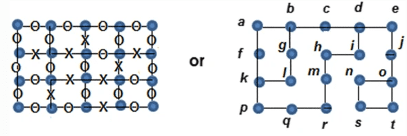
Figure 1 below shows the two types of notations the paper uses:
Figure 1
On the left is the "OXO" notation that we will use to describe the paths. The notation on the right will be the primary notation used in the figures of this blog.
In the "OXO" notation, an "O" denotes an edge, and an "X" denotes an edge that has been deleted, and that there is not connection present between the vertices at both ends of an "X" edge. A typical path where the vertices are connected with existing edges would appear as "OOOO" where there are 5 vertices between the 4 "O" edges.
In this case, we are more interested in paths where the edges alternate between "O" and "X" called an Alternate Edge Path. An alternate edge path can start with either an "O" or an "X", thus it can take the form of "XOXO..." or "OXOX...". A reflection of a path is simply its inverse which changes "O"s to "X"s and vice versa. So a path "XOXO" is reflected to become "OXOX".
There are two special types of alternate edge paths that we are interested in:
- Connector: This is an alternate edge path that starts and ends that the same vertex producing a cycle, and also has an even number of EDGES.
- Destroyer: This is an alternate edge path that must start and end an "O". As a result, it will also always have an odd number of EDGES.
Stages
The algorithm has 3 stages to it, Deletion, Destroyer Reflections, and Connector Reflections.
Deletion
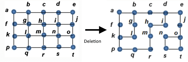
In the Deletion stage, we start with a fully connected graph, and we randomly delete edges for each vertex such that their own or their neighbor's number of edges do not fall below 2. Any vertices that have edges that can be deleted based on this requirement are said the have surplus edges. Figure 2 below shows a graph before and after this stage:
Figure 2
While ideally we end up only with vertices that only have 2 edges each, most of the time there will be vertices that have 3 edges. These edges are placed into a set called the Remainder Set. I haven't encountered a case where a vertex has all 4 edges remaining.
Destroyer Reflection
The purpose of this stage is to reduce the number of edges for each vertex in the remainder set down from 3 to 2. This is accomplished by finding a Destroyer paths between any two vertices in the remainder set, and then reflecting the path in place, reducing the number of edges at each end of the path by 1 without affecting the number of edges for any other vertex in the path. This is because one edge is added to each vertex while another is simultaneously removed, the addition does not occur at the start and end of the path.
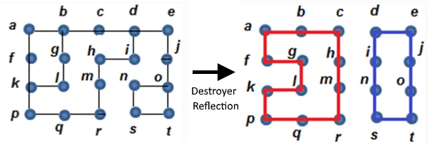
In graph in Figure 2, we have the remainder set of vertices: {b,d,k,o}. It was arbitrarily decided that the vertices b and k will be paired up. There exists a destroyer path P: (b,g,f,k) with edges "OXO". With the remaining vertices d and o we have destroyer path Q: (d,c,h,i,n,o) with edges "OXOXO". Note that there could be other paths that could be used, but these were just arbitrarily chosen. Figure 3 shows the result of reflecting paths P and Q:
Figure 3
There are no more vertices with 3 edges, just unconnected cycles. This is the state the graph needs to be in in order to start the next stage.
Connector Reflection
This stage is the one that produces the Hamiltonian Cycle. By searching for and reflecting connector paths in the graph, this process will eventually result in the unconnected cycles in the graph joining together to form a HC. I say eventually because even in the paper, they are essentially doing a depth first search and trying every combination until they find something.
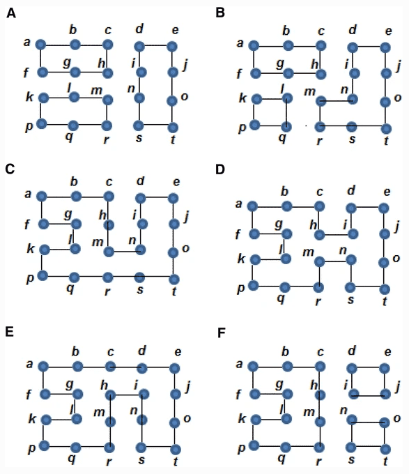
Lets assume that we performed a search and we found connector path R: (g,h,m,l,g) with edges "XOXO". When we reflect R, the graph will take the form of graph A in figure 4 below. The rest are the result of applying paths S: (q,l,g,h,m,n,s,r,q), T: (m,n,s,r,m), U: (h,i,n,m,h), V: (c,d,i,h,c) and W: (i,j,o,n,i) in order. Reflecting connectors preserves the number of edges of each vertex but changes the status of the graph from a representation to another.
Figure 4
The paper presents all paths at the same time, which I initially interpreted as them finding these paths while in the state shown in figure 3, and that reflection can be performed in any order. However this is not the case as path T is not a valid connector path in graph B. Thus my interpretation is now that we should find a connector, reflect it, and then search again after each reflection.
Implementation
Building a Cycle
A Hamiltonian Cycle is created simply by calling the buildCycle() function, passing in the the dimensions of the graph and the locations of walls.
const buildCycle = (nx, ny, exclusions=NodeSet(),
    findDestroyerStepLimit=0, findConnectorStepLimit=100,
    findConnectorIterLimit=100) => {
  let graph = fnHamiltonian.mkGraph(nx, ny)
  fnHamiltonian.processExclusions(graph, exclusions)
  fnHamiltonian.runDeletion(graph)
  fnHamiltonian.getDestroyerPaths(graph, findDestroyerStepLimit)
    .forEach(p => fnHamiltonian.invertPath(p))
  fnHamiltonian.invertConnectorPaths(graph, findConnectorStepLimit, findConnectorIterLimit)
  return graph
}
Each step in this function basically represents the stages laid out in the Concepts section of this blog.
Vertex
In this implementation, I decided to have a Vertex be a subclass of a game Node with additional methods for mutating its edges. These methods are simple
and self explanatory, but keep in mind that vx.invertEdge() and vx.deleteEdge() mutate the edges of their applicable neighbors as well.
Edges can have 3 values:
- -1 : Does not exist, this is used when an edge should never be used, such as at the boundary of the play area, or the edges connecting to a wall.
- 1 : Exists, this is used to denote an edge that is present and connects the vertices at both its ends.
- 0 : Inactive, this is used when an edge is not in use, but its value can be set to 1 again for use if needed.
mkGraph() and processExclusions()
A graph in this case is a 2D matrix of Vertex objects where each edge is initialized to 1, and edges at boundaries are set to -1.
const mkGraph = (nx, ny) => {
  const graph = Array.from(Array(nx), _ => Array.from(Array(ny), _ => null))
  // 1 for edge, 0 for deleted edge, -1 for no edge
  for (let i=0; i<graph.length; i++) {
    for (let j=0; j<graph[i].length; j++) {
      graph[i][j] = fnHamiltonian.Vertex(i, j, graph)
      // No edges at the ends of the graph
      if (i==0) graph[i][j].deleteEdge(game.WEST)
      else if (i==graph.length-1) graph[i][j].deleteEdge(game.EAST)
      if (j==0) graph[i][j].deleteEdge(game.NORTH)
      else if (j==graph[i].length-1) graph[i][j].deleteEdge(game.SOUTH)
    }
  }
  return graph
}
After a graph is created, vertices that are in the exclusions NodeSet are removed by setting all their edges to -1. This is used
to represent walls in the the play area.
const processExclusions = (graph, exclusions) => {
  exclusions.lookup.forEach(node => {
    game.DIRECTIONS.forEach(d => graph[node.x][node.y].deleteEdge(d))
  })
}
runDeletion()
This corresponds to the Deletion stage of the algorithm. It iterates through the graph deleting edges in random order so that there are no surplus edges remaining in the graph by the end of the operation.
const runDeletion = graph => {
  for (let i=0; i<graph.length; i++) {
    for (let j=0; j<graph[i].length; j++) {
      const vx = graph[i][j]
      const ord = game.DIRECTIONS.concat()
      utils.shuffle(ord)
      for (let k=0 ; k<ord.length; k++) {
        if(vx.nEdges<=2) break
        else if (vx.getEdge(ord[k])>0 && vx.getNeighbor(ord[k]).nEdges>2) {
          vx.invertEdge(ord[k])
        }
      }
    }
  }
}
getDestroyerPaths()
This searches a graph that has already been through a Deletion operation for the vertices that have more than 2 edges and generates a remainder set. It then iterates through the set, running a breadth first search to find the shortest destroyer path connecting two vertices in the set until all vertices have been paired up.
const getDestroyerPaths = (graph, stepLimit=0) => {
  const remainders = fnHamiltonian.getRemainders(graph)
  const remCopy = remainders.copy()
  const paths = []
  remainders.lookup.forEach(vx => {
    if (remCopy.hasNode(vx))
      paths.push(fnHamiltonian.findDestroyer(graph, vx, remCopy, stepLimit))
  })
  return paths
}
The paths found by the function are then inverted to reduce the number of edges for the start and end vertices of each path from 3 to 2. This will result in a graph that only contains vertices with 2 edges.
I found that in general, paths for which a HC can be generated will have an even number of remainder vertices and they can all be paired with another to fully eliminate the set.
invertConnectorPaths()
This searches the graph for connector paths, reflects them and then checks if there is a Hamiltonian Cycle. In the paper they performed a brute force search, but I found that picking a random point to start from tended to yield faster results.
const invertConnectorPaths = (graph, stepLimit=0, iterationLimit=100) => {
  for(let i=0; i<iterationLimit; i++) {
    const start = graph[utils.randInt(0, graph.length-1)][utils.randInt(0, graph[0].length-1)]
    const goals = NodeSet()
    goals.addNode(start)
    fnHamiltonian.invertPath(fnHamiltonian.findConnector(graph, start, goals, stepLimit))
    if(fnHamiltonian.isHamiltonianCycle(graph)) break
  }
}
Ultimately this section of the algorithm will have to keep going until it finds a HC, which can be instant, take forever, or anywhere in between. So there is still a lot of room for improvement.


